فعالیتهای گروه مهندسین پویش انرژی

1-طراحی و ساخت انواع تابلوهای برق فشار ضعیف، فشار متوسط، کنترل و بانک خازن , تابلو دیزل ژنراتور

2-مشاوره ، طراحی ،محاسبات و تهیه انواع نقشه های تاسیسات برق و مکانیک ساختمان مسکونی،

اداری، تجاری ، صنعتی و بیمارستان مطابق با استانداردهای نظام مهندسی.

ایمیل : peeg.co@gmail.com

جدول تعاریف درجه حفاظت (IP)

رقم مشخصه اول   IP X—میزان حفاظت در برابر ورود اشیا خارجی

جزئیات نوع حفاظت ایجاد شده توسط پوشش دستگاه

شرح مختصر

شماره

حفاظت ویژه ای ندارد

حفاظت نشده

0

دارای حفاظت برای اعضای بزرگ بدن انسان مانند دست (ولی فاقد حفاظت در برابر دسترسی عمدی). دارای حفاظت برای اجسام بیش از 50 میلیمتر

حفاظت در برابر اجسام سخت بزرگتر از 50 میلیمتر

1

دارای حفاظت برای انگشتان یا اجسامی كه طول آن از 80 میلیمتر متجاوز نباشد. دارای حفاظت برای اجسام بیش از 12 میلیمتر

حفاظت در برابر اجسام سخت بزرگتر از 12 میلیمتر

2

دارای حفاظت برای ابزار ها، سیم ها و غیره با قطر یا با ضخامت بیش از 2.5 میلیمتر. دارای حفاظت برای اجسام سخت با قطر بیش از 2.5 میلیمتر

حفاظت در برابر اجسام سخت بزرگتر از 2.5 میلیمتر

3

دارای حفاظت برای سیمها یا تسمه ها با ضخامت بیش از یك میلیمتر. دارای حفاظت برای اجسام سخت با قطر بیش از 1.5 میلیمتر

حفاظت در برابر اجسام سخت بزرگتر از 1.5 میلیمتر

4

از نفوذ گرد و غبار به درون دستگاه كاملا جلوگیری نشده است اما گرد و غبار به میزانی كه در كار دستگاه ایجاد اختلال كند وارد نمی شود.

حفاظت در برابر گرد و غبار

5

هیچ گونه گرد و غبار نفوذ نمی كند.

غیر قابل نفوذ در برابر گرد و غبار

6

مثال: موتوری با IP57 در برابر گرد و غبار به طور كامل حفاظت شده نیست اما از ورود گرد غبار تا اندازه ای قابل قبول جلوگیری می كند.


رقم مشخصه دوم   IP— X میزان حفاظت در برابر ورود رطوبت به داخل دستگاه

جزئیات نوع حفاظت ایجاد شده توسط پوشش دستگاه

شرح مختصر

شماره

حفاظت ویژه ای ندارد

حفاظت نشده

0

چكیدن آب (ریزش عمودی قطرات آب) اثر زیان آوری ندارد

حفاظت شده در برابر چكیدن آب

1

چكیدن قطرات عمودی آب بر پوشش با زاویه انحراف تا 15 درجه اثر زیان آوری نخواهد داشت

حفاظت شده در برابر چكیدن آب با زاویه انحراف تا 15 درجه

2

بارش آب به صورت پاشیدگی تا زاویه 60 درجه از وضع قائم اثر زیان آوری نخواهد داشت

حفاظت شده در برابر پاشیدگی آب تا 60 درجه

3

آب ترشح شده از هر سو به پوشش دستگاه اثر زیان آوری نخواهد داشت.

حفاظت شده در برابر ترشح آب

4

آب پرتاب شده توسط آب پخش كن از هر سو به پوشش دستگاه اثر زیان آوری نخواهد داشت

حفاظت شده در برابر فوران آب

5

آب حاصله از امواج دریای طوفانی یا فوران شدید آب نمی تواند به مقدار زیان آور وارد دستگاه شود.

حفاظت شده در برابر امواج دریا

6

هنگامی كه پوشش دستگاه در شرایط معینی از فشار و زمان در آب غوطه ور می شود نباید نفوذ آب به مقدار زیان آوری در آن امكان پذیر باشد.

حفاظت شده در برابر اثرات غوطه ور شدن در آب

7

تجهیزات در برابر فرورفتگی مداوم در زیر آب تحت شرایطی كه به وسیله سازنده مشخص می شود مناسب است.

حفاظت شده در برابر فرورفتگی در زیر آب

8

مثال: موتوری با IP57 در برابر نفوذ رطوبت یك حفاظت قابل قبولی را برای كاربرد در شرایط ساحلی دارد ولی برای مدت زیادی در آب نمی تواند بماند.


منبع: نشریه 110 جلد اول

شدت روشنایی توصیه شده به لوکس


اتاقهای اداری300

اتاقهای اداری گروهی500

اتاقهای اداری بزرگ750

دفتر نقشه کشی فنی750

رایانه500

امور بازرسی و کنترل200

راهرو50

پلکان100

کانتین200

دستشویی100

فروشگاهها200

سوپر مارکت500

رستوران200

کافه تریا200

فروشگاههای سلف سرویس300

آشپزخانه های بزرگ 500

موزه با گالری200

نمایشگاه (غرفه و سالن)300

کتابخانه300

اتاق مطالعه500

سالن ورزشی400

آزمایشگاه500

آرایشگاه750

بیمارستان300

کلاس درس300-500

کلاس درس بزرگ750

مسجد200

سالن کنفرانس500

اتاق با کاربردهای مختلف300

سالن کنسرت و تاتر300

اتاق جلسات300

(Bus Switching Configurations In Air Insulated Substations (AIS


Bus Switching Configurations In Air Insulated Substations
(AIS)

Various factors affect the reliability of a substation, one of which is the arrangement of the switching devices. Arrangement of the switching devices will impact maintenance, protection, initial substation development, and cost.

There are six types of substation bus switching arrangements commonly used in air insulated substations:

1. Single bus
2. Double bus, double breaker
3. Main and transfer (inspection) bus
4. Double bus, single breaker
5. Ring bus
6. Breaker and a half


1. Single Bus Configuration

This arrangement involves one main bus with all circuits connected directly to the bus. The reliability of this type of an arrangement is very low. When properly protected by relaying, a single failure to the main bus or any circuit section between its circuit breaker and the main bus will cause an outage of the entire system. In addition, maintenance of devices on this system requires the de-energizing of the line connected to the device.

Maintenance of the bus would require the outage of the total system, use of standby generation, or switching to adjacent station, if available. Since the single bus arrangement is low in reliability, it is not recommended for heavily loaded substations or substations having a high availability requirement.

Reliability of this arrangement can be improved by the addition of a bus tiebreaker to minimize the effect of a main bus failure.


2. Double Bus, Double Breaker Configuration


This scheme provides a very high level of reliability by having two separate breakers available to each circuit. In addition, with two separate buses, failure of a single bus will not impact either line. Maintenance of a bus or a circuit breaker in this arrangement can be accomplished without interrupting either of the circuits.

This arrangement allows various operating options as additional lines are added to the arrangement; loading on the system can be shifted by connecting lines to only one bus. A double bus, double breaker scheme is a high-cost arrangement, since each line has two breakers and requires a larger area for the substation to accommodate the additional equipment. This is especially true in a low profile configuration.

The protection scheme is also more involved than a single bus scheme.


3. Main and Transfer Bus Configuration


This scheme is arranged with all circuits connected between a main (operating) bus and a transfer bus (also referred to as an inspection bus). Some arrangements include a bus tie breaker that is connected between both buses with no circuits connected to it.

Since all circuits are connected to the single, main bus, reliability of this system is not very high. However, with the transfer bus available during maintenance, de-energizing of the circuit can be avoided. Some systems are operated with the transfer bus normally de-energized. When maintenance work is necessary, the transfer bus is energized by either closing the tie breaker, or when a tie breaker is not installed, closing the switches connected to the transfer bus. With these switches closed, the breaker to be maintained can be opened along with its isolation switches. Then the breaker is taken out of service. The circuit breaker remaining in service will now be connected to both circuits through the transfer bus.

This way, both circuits remain energized during maintenance. Since each circuit may have a different circuit configuration, special relay settings may be used when operating in this abnormal arrangement.

When a bus tie breaker is present, the bus tie breaker is the breaker used to replace the breaker being maintained, and the other breaker is not connected to the transfer bus. A shortcoming of this scheme is that if the main bus is taken out of service, even though the circuits can remain energized through the transfer bus and its associated switches, there would be no relay protection for the circuits. Depending on the system arrangement, this concern can be minimized through the use of circuit protection devices (reclosure or fuses) on the lines outside the substation.

This arrangement is slightly more expensive than the single bus arrangement, but does provide more flexibility during maintenance. Protection of this scheme is similar to that of the single bus arrangement. The area required for a low profile substation with a main and transfer bus scheme is also greater than that of the single bus, due to the additional switches and bus.


4. Double Bus, Single Breaker Configuration


This scheme has two main buses connected to each line circuit breaker and a bus tie breaker. Utilizing the bus tie breaker in the closed position allows the transfer of line circuits from bus to bus by means of the switches. This arrangement allows the operation of the circuits from either bus. In this arrangement, a failure on one bus will not affect the other bus.

However, a bus tie breaker failure will cause the outage of the entire system. Operating the bus tie breaker in the normally open position defeats the advantages of the two main buses. It arranges the system into two single bus systems, which as described previously, has very low reliability. Relay protection for this scheme can be complex, depending on the system requirements, flexibility, and needs.

With two buses and a bus tie available, there is some ease in doing maintenance, but maintenance on line breakers and switches would still require outside the substation switching to avoid outages.


5. Ring Bus Configuration


In this scheme, as indicated by the name, all breakers are arranged in a ring with circuits tapped between breakers. For a failure on a circuit, the two adjacent breakers will trip without affecting the rest of the system. Similarly, a single bus failure will only affect the adjacent breakers and allow the rest of the system to remain energized. However, a breaker failure or breakers that fail to trip will require adjacent breakers to be tripped to isolate the fault.

Maintenance on a circuit breaker in this scheme can be accomplished without interrupting any circuit, including the two circuits adjacent to the breaker being maintained. The breaker to be maintained is taken out of service by tripping the breaker, then opening its isolation switches. Since the other breakers adjacent to the breaker being maintained are in service, they will continue to supply the circuits. In order to gain the highest reliability with a ring bus scheme, load and source circuits should be alternated when connecting to the scheme.

Arranging the scheme in this manner will minimize the potential for the loss of the supply to the ring bus due to a breaker failure. Relaying is more complex in this scheme than some previously identified. Since there is only one bus in this scheme, the area required to develop this scheme is less than some of the previously discussed schemes. However, expansion of a ring bus is limited, due to the practical arrangement of circuits.


6. Breaker-and-a-Half Configuration


The breaker-and-a-half scheme can be developed from a ring bus arrangement as the number of circuits increases. In this scheme, each circuit is between two circuit breakers, and there are two main buses. The failure of a circuit will trip the two adjacent breakers and not interrupt any other circuit. With the three breaker arrangement for each bay, a center breaker failure will cause the loss of the two adjacent circuits. However, a breaker failure of the breaker adjacent to the bus will only interrupt one circuit.

Maintenance of a breaker on this scheme can be performed without an outage to any circuit. Further- more, either bus can be taken out of service with no interruption to the service. This is one of the most reliable arrangements, and it can continue to be expanded as required. Relaying is more involved than some schemes previously discussed.

This scheme will require more area and is costly due to the additional components.


Comparison table of configurations:

ConfigurationReliabilityCostAvailable area
.Single busLeast reliable — single failure can cause complete outageLeast cost — fewer componentsLeast area — fewer components
.Double busHighly reliable — duplicated components; single failure normally isolates single componentHigh cost — duplicated componentsGreater area — twice as many components
.Main bus and .transferLeast reliable — same as
Single bus, but flexibility in operating and maintenance with transfer bus
Moderate cost — fewer componentsLow area requirement —  fewer components
.Double bus, .single breakerModerately reliable — depends on arrangement of components and busModerate cost — more componentsModerate area — more components
.Ring busHigh reliability — single failure isolates single componentModerate cost — more componentsModerate area — increases with number of circuits
.Breaker and a.halfHighly reliable — single circuit failure isolates single circuit, bus failures do not affect circuitsModerate cost — breaker-and-a-half for each circuitGreater area — more components per circuit

What is the difference between MCB, MCCB, ELCB, and RCCB

What is the difference between MCB, MCCB, ELCB, and RCCB

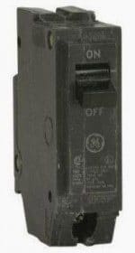
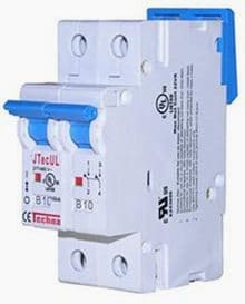
MCB (Miniature Circuit Breaker)

MCB (Miniature Circuit Breaker)

Characteristics
  • Rated current not more than 100 A.
  • Trip characteristics normally not adjustable.
  • Thermal or thermal-magnetic operation.

MCCB (Moulded Case Circuit Breaker)

MCCB (Moulded Case Circuit Breaker)

Characteristics
  • Rated current up to 1000 A.
  • Trip current may be adjustable.
  • Thermal or thermal-magnetic operation.

Air Circuit Breaker

Characteristics
  • Rated current up to 10,000 A.
  • Trip characteristics often fully adjustable including configurable trip thresholds and delays.
  • Usually electronically controlled—some models are microprocessor controlled.
  • Often used for main power distribution in large industrial plant, where the breakers are arranged in draw-out enclosures for ease of maintenance.

Vacuum Circuit Breaker

Characteristics
  • With rated current up to 3000 A,
  • These breakers interrupt the arc in a vacuum bottle.
  • These can also be applied at up to 35,000 V. Vacuum circuit breakers tend to have longer life expectancies between overhaul than do air circuit breakers.

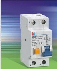
RCD (Residual Current Device / RCCB(Residual Current Circuit Breaker)

RCCB - Residual Current Circuit Breaker

Characteristics
  • Phase (line) and Neutral both wires connected through RCD.
  • It trips the circuit when there is earth fault current.
  • The amount of current flows through the phase (line) should return through neutral .
  • It detects by RCD. any mismatch between two currents flowing through phase and neutral detect by -RCD and trip the circuit within 30Miliseconed.
  • If a house has an earth system connected to an earth rod and not the main incoming cable, then it must have all circuits protected by an RCD (because u mite not be able to get enough fault current to trip a MCB)
  • RCDs are an extremely effective form of shock protection

The most widely used are 30 mA (milliamp) and 100 mA devices. A current flow of 30 mA (or 0.03 amps) is sufficiently small that it makes it very difficult to receive a dangerous shock. Even 100 mA is a relatively small figure when compared to the current that may flow in an earth fault without such protection (hundred of amps)

A 300/500 mA RCCB may be used where only fire protection is required. eg., on lighting circuits, where the risk of electric shock is small.

Limitation of RCCB

  • Standard electromechanical RCCBs are designed to operate on normal supply waveforms and cannot be guaranteed to operate where none standard waveforms are generated by loads. The most common is the half wave rectified waveform sometimes called pulsating dc generated by speed control devices, semi conductors, computers and even dimmers.
  • Specially modified RCCBs are available which will operate on normal ac and pulsating dc.
  • RCDs don’t offer protection against current overloads: RCDs detect an imbalance in the live and neutral currents. A current overload, however large, cannot be detected. It is a frequent cause of problems with novices to replace an MCB in a fuse box with an RCD. This may be done in an attempt to increase shock protection. If a live-neutral fault occurs (a short circuit, or an overload), the RCD won’t trip, and may be damaged. In practice, the main MCB for the premises will probably trip, or the service fuse, so the situation is unlikely to lead to catastrophe; but it may be inconvenient.
  • It is now possible to get an MCB and and RCD in a single unit, called an RCBO (see below). Replacing an MCB with an RCBO of the same rating is generally safe.
  • Nuisance tripping of RCCB: Sudden changes in electrical load can cause a small, brief current flow to earth, especially in old appliances. RCDs are very sensitive and operate very quickly; they may well trip when the motor of an old freezer switches off. Some equipment is notoriously `leaky’, that is, generate a small, constant current flow to earth. Some types of computer equipment, and large television sets, are widely reported to cause problems.
  • RCD will not protect against a socket outlet being wired with its live and neutral terminals the wrong way round.
  • RCD will not protect against the overheating that results when conductors are not properly screwed into their terminals.
  • RCD will not protect against live-neutral shocks, because the current in the live and neutral is balanced. So if you touch live and neutral conductors at the same time (e.g., both terminals of a light fitting), you may still get a nasty shock.

ELCB (Earth Leakage Circuit Breaker)

ELCB (Earth Leakage Circuit Breaker)

Characteristics
  • Phase (line), Neutral and Earth wire connected through ELCB.
  • ELCB is working based on Earth leakage current.
  • Operating Time of ELCB: 
    • The safest limit of Current which Human Body can withstand is 30ma sec.
    • Suppose Human Body Resistance is 500Ω and Voltage to ground is 230 Volt.
    • The Body current will be 500/230=460mA.
    • Hence ELCB must be operated in  30maSec/460mA = 0.65msec

RCBO (Residual Circuit Breaker with OverLoad)

  • It is possible to get a combined MCB and RCCB in one device (Residual Current Breaker with Overload RCBO), the principals are the same, but more styles of disconnection are fitted into one package

Difference between ELCB and RCCB

  • ELCB is the old name and often refers to voltage operated devices that are no longer available and it is advised you replace them if you find one.
  • RCCB or RCD is the new name that specifies current operated (hence the new name to distinguish from voltage operated).
  • The new RCCB is best because it will detect any earth fault. The voltage type only detects earth faults that flow back through the main earth wire so this is why they stopped being used.
  • The easy way to tell an old voltage operated trip is to look for the main earth wire connected through it.
  • RCCB will only have the line and neutral connections.
  • ELCB is working based on Earth leakage current. But RCCB is not having sensing or connectivity of Earth, because fundamentally Phase current is equal to the neutral current in single phase. That’s why RCCB can trip when the both currents are deferent and it withstand up to both the currents are same. Both the neutral and phase currents are different that means current is flowing through the Earth.
  • Finally both are working for same, but the thing is connectivity is difference.
  • RCD does not necessarily require an earth connection itself (it monitors only the live and neutral).In addition it detects current flows to earth even in equipment without an earth of its own.
  • This means that an RCD will continue to give shock protection in equipment that has a faulty earth. It is these properties that have made the RCD more popular than its rivals. For example, earth-leakage circuit breakers (ELCBs) were widely used about ten years ago. These devices measured the voltage on the earth conductor; if this voltage was not zero this indicated a current leakage to earth. The problem is that ELCBs need a sound earth connection, as does the equipment it protects. As a result, the use of ELCBs is no longer recommended.

MCB Selection

  • The first characteristic is the overload which is intended to prevent the accidental overloading of the cable in a no fault situation. The speed of the MCB tripping will vary with the degree of the overload. This is usually achieved by the use of a thermal device in the MCB.
  • The second characteristic is the magnetic fault protection, which is intended to operate when the fault reaches a predetermined level and to trip the MCB within one tenth of a second. The level of this magnetic trip gives the MCB its type characteristic as follows:

    TypeTripping CurrentOperating Time
    Type B3 To 5 time full load current0.04 To 13 Sec
    Type C5 To 10 times full load current0.04 To 5 Sec
    Type D10 To 20 times full load current0.04 To 3 Sec
  • The third characteristic is the short circuit protection, which is intended to protect against heavy faults maybe in thousands of amps caused by short circuit faults.
  • The capability of the MCB to operate under these conditions gives its short circuit rating in Kilo amps (KA). In general for consumer units a 6KA fault level is adequate whereas for industrial boards 10KA fault capabilities or above may be required.

Fuse and MCB characteristics

  • Fuses and MCBs are rated in amps. The amp rating given on the fuse or MCB body is the amount of current it will pass continuously. This is normally called the rated current or nominal current.
  • Many people think that if the current exceeds the nominal current, the device will trip, instantly. So if the rating is 30 amps, a current of 30.00001 amps will trip it, right? This is not true.
  • The fuse and the MCB, even though their nominal currents are similar, have very different  properties.
  • For example, For 32Amp MCB and 30 Amp Fuse, to be sure of tripping in 0.1 seconds, the MCB requires a current of 128 amps, while the fuse requires 300 amps.
  • The fuse clearly requires more current to blow it in that time, but notice how much bigger both these currents are than the ’30 amps’ marked current rating.
  • There is a small likelihood that in the course of, say, a month, a 30-amp fuse will trip when carrying 30 amps. If the fuse has had a couple of overloads before (which may not even have been noticed) this is much more likely. This explains why fuses can sometimes ‘blow’ for no obvious reason
  • If the fuse is marked ’30 amps’, but it will actually stand 40 amps for over an hour, how can we justify calling it a ’30 amp’ fuse? The answer is that the overload characteristics of fuses are designed to match the properties of modern cables. For example, a modern PVC-insulated cable will stand a 50% overload for an hour, so it seems reasonable that the fuse should as well.